2-Stage Reduction Gearbox
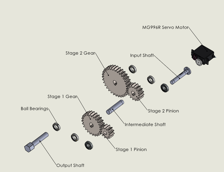
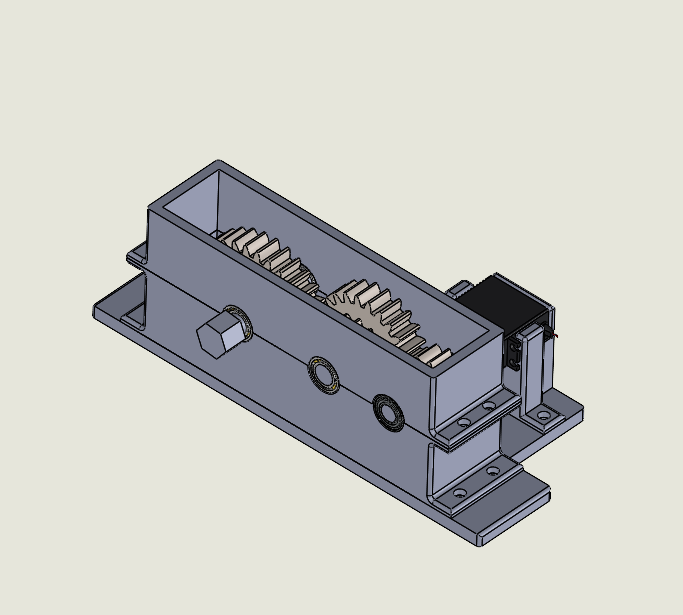
The inspiration for this project came from me attempting to build a robotic arm but not having a powerful enough servo motor on hand for the base joint, which requires the highest amount of torque. So, I decided to create a 2-stage 4:1 reduction gearbox in a compact space, to amplify the torque output of a MG 996R servo motor. I was fully responsible for all aspects of this project.
I first started by designing a single-stage 2:1 reduction gearbox, then after validating its performance extended the design to a 2-stage gearbox.
Skills Utilized 🔨
Mechanical Design
3D Printing
Design for Assembly
Fits and Tolerances
Requirements (Single Stage)
Must be able to able to output at least 14.88 kg · cm of torque, from a 9.4 kg · cm input servo motor
All components except fasteners and bearings must be 3D printable and have a minimum safety factor 1.5 for all loads they support
Must be contained within a space of 150×150×150 mm
Engineering Challenges
Balancing shaft size, gear module size and number of teeth to fit in as small of a space as possible
Defining assembly steps and tolerances for the bearings, shaft and the gears
Initial Ideas, Sketches
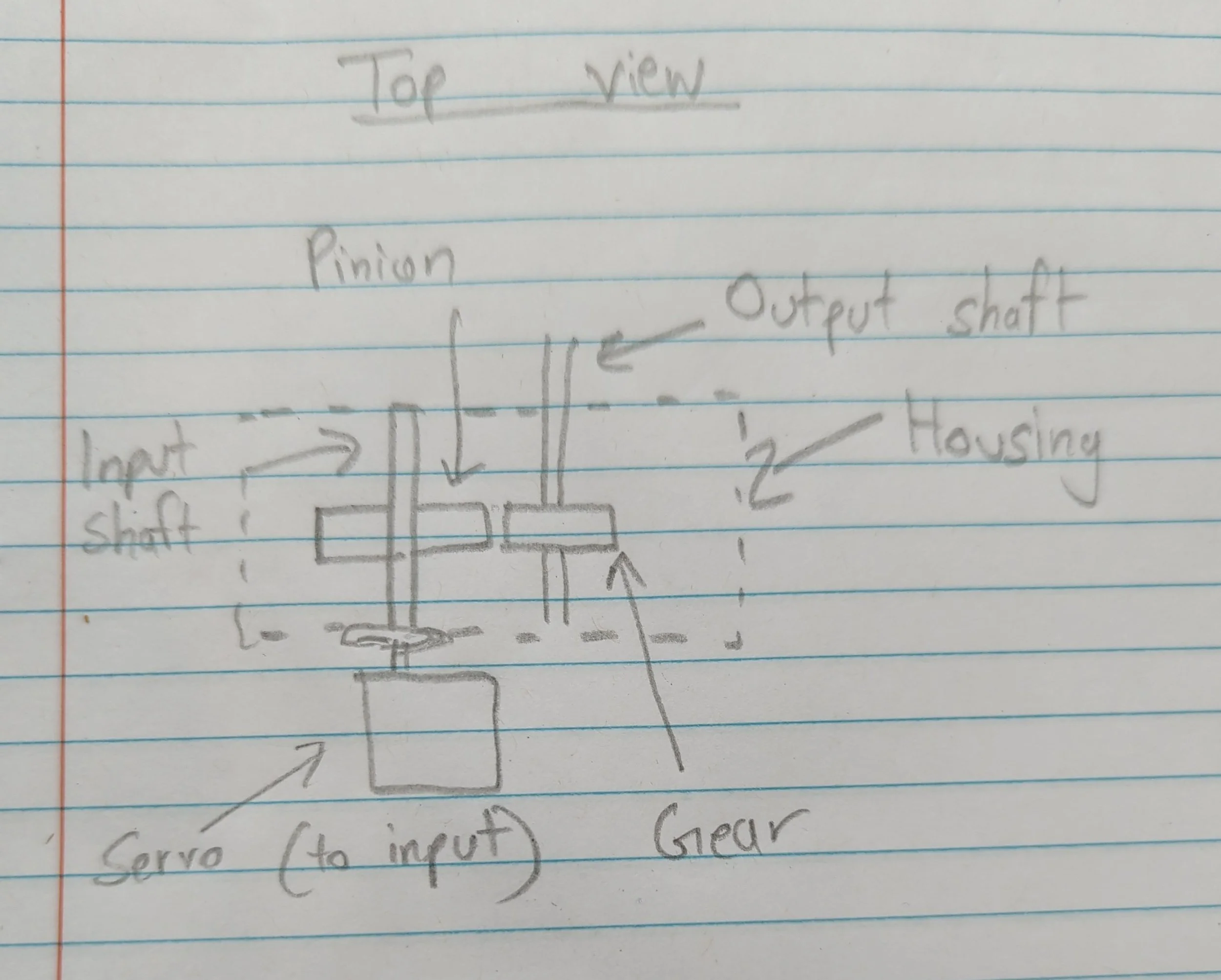
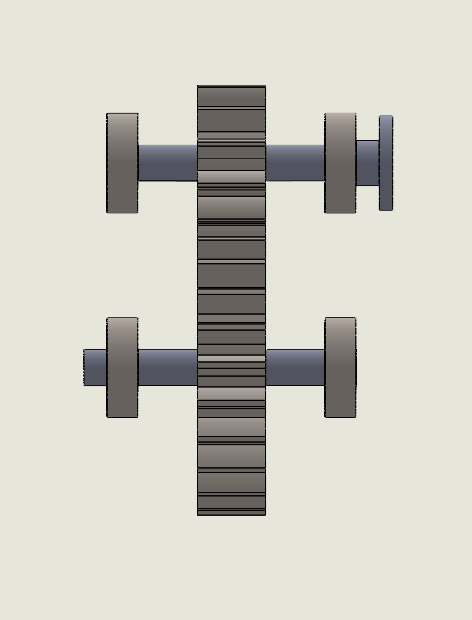
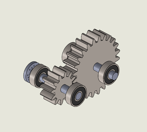
Calculations
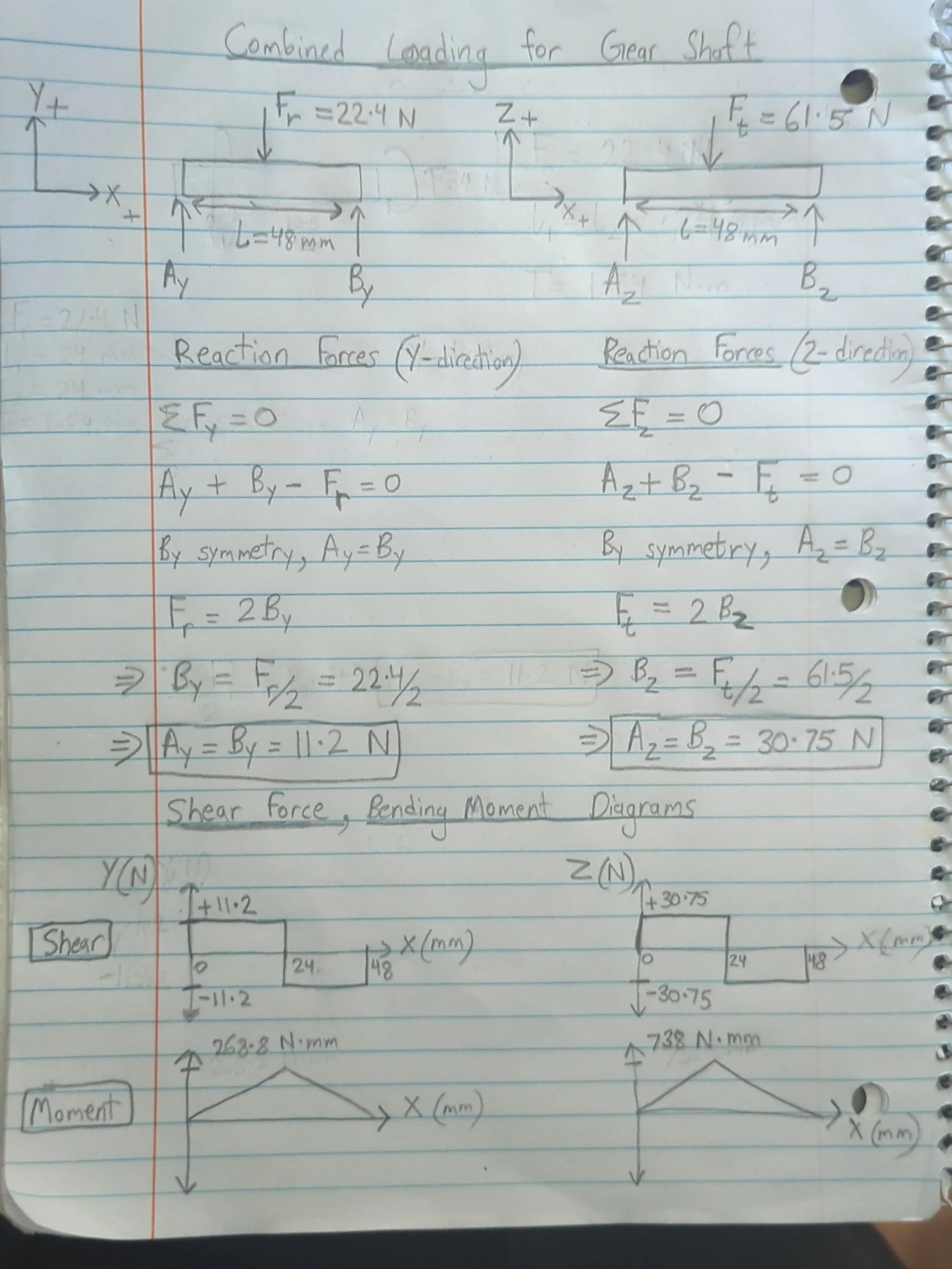
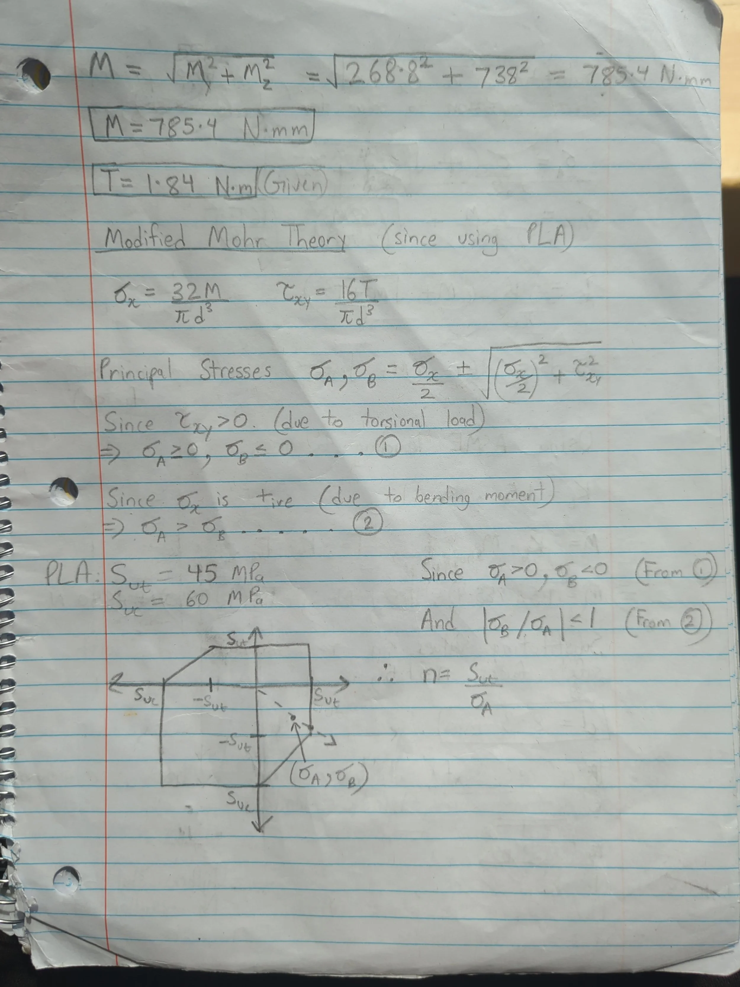
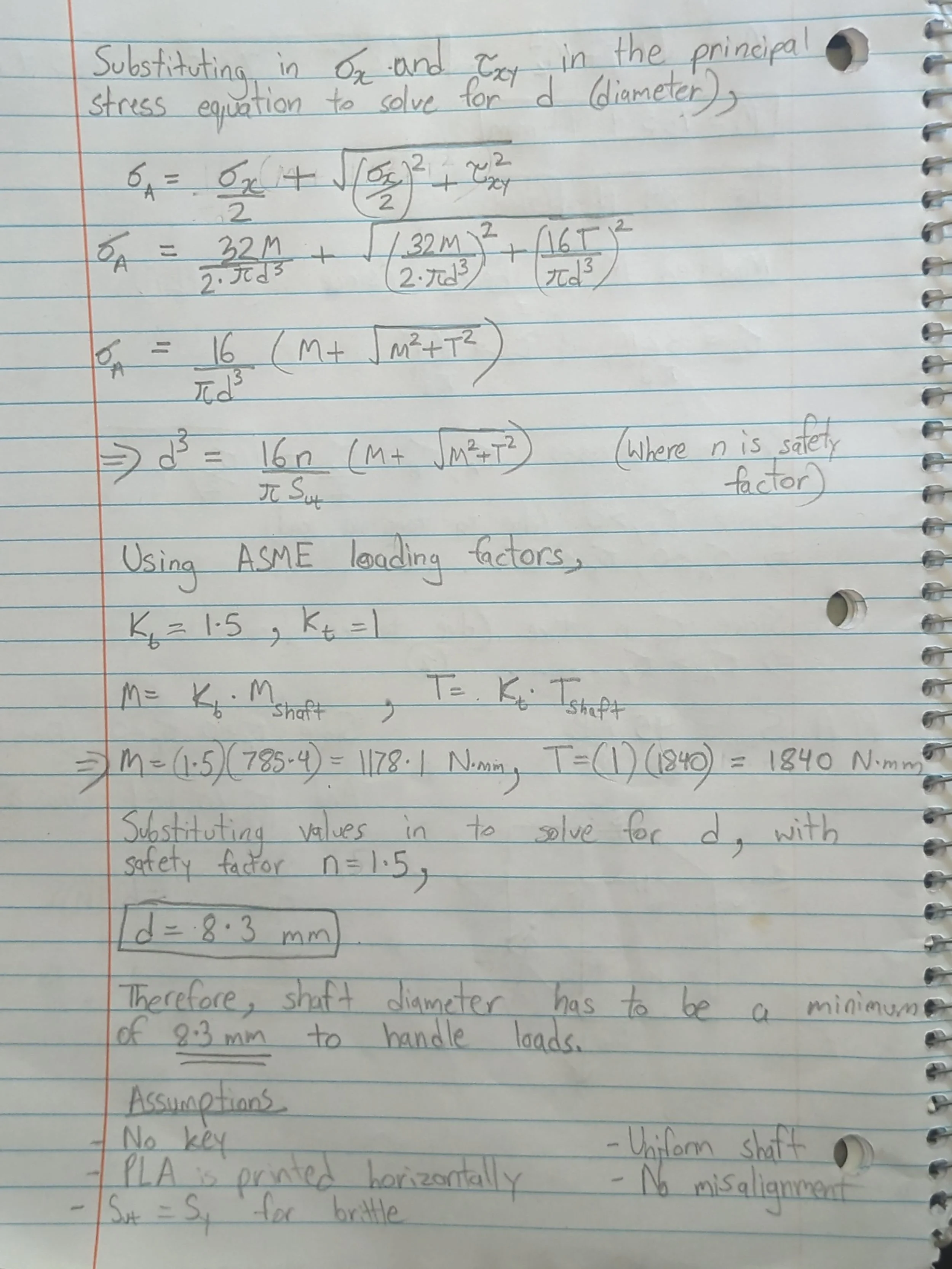
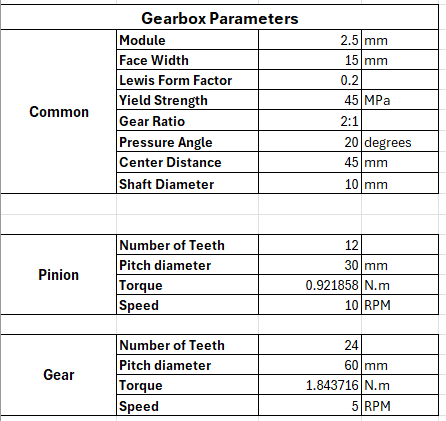
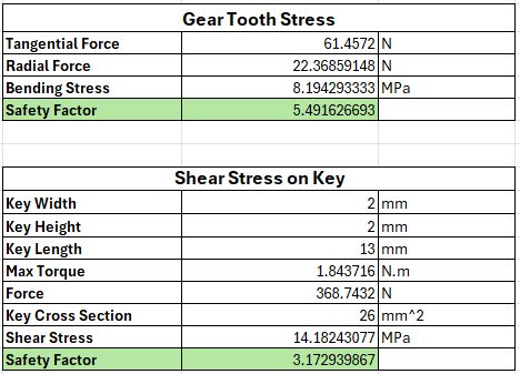
The hand calculations to find the minimum diameter of the gear shaft (which is under the highest load) is shown below, along with the safety factors for the gear teeth and keys (found using Excel).
Final CAD
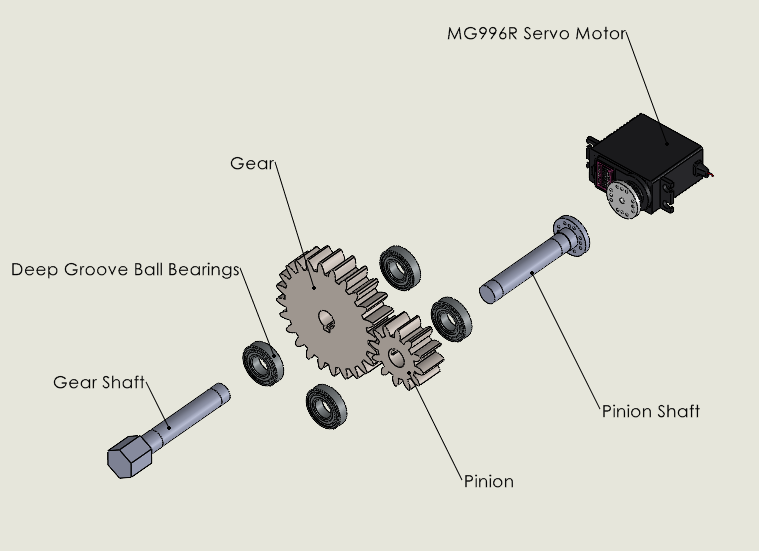
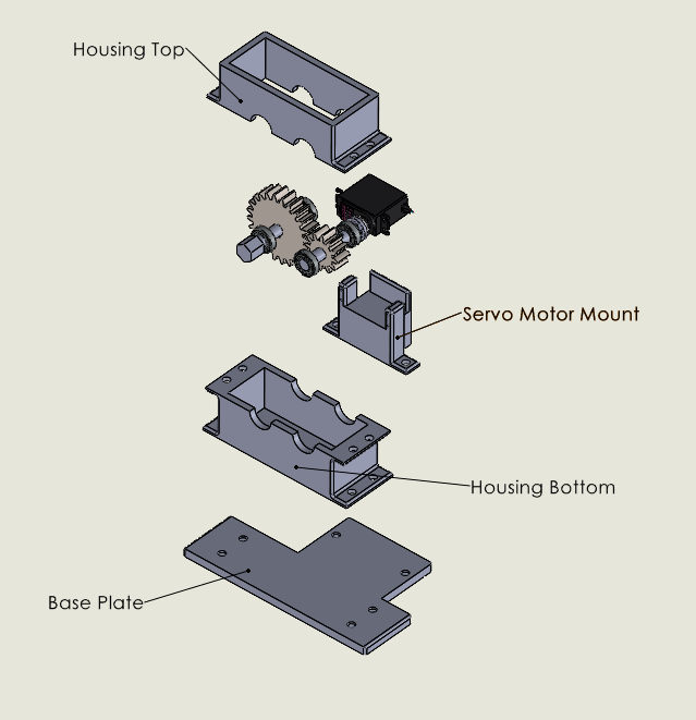
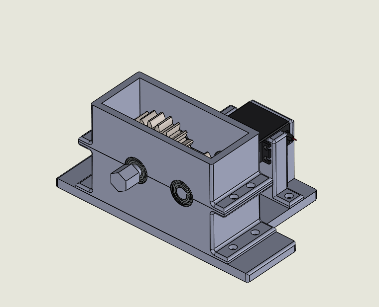
Prototype
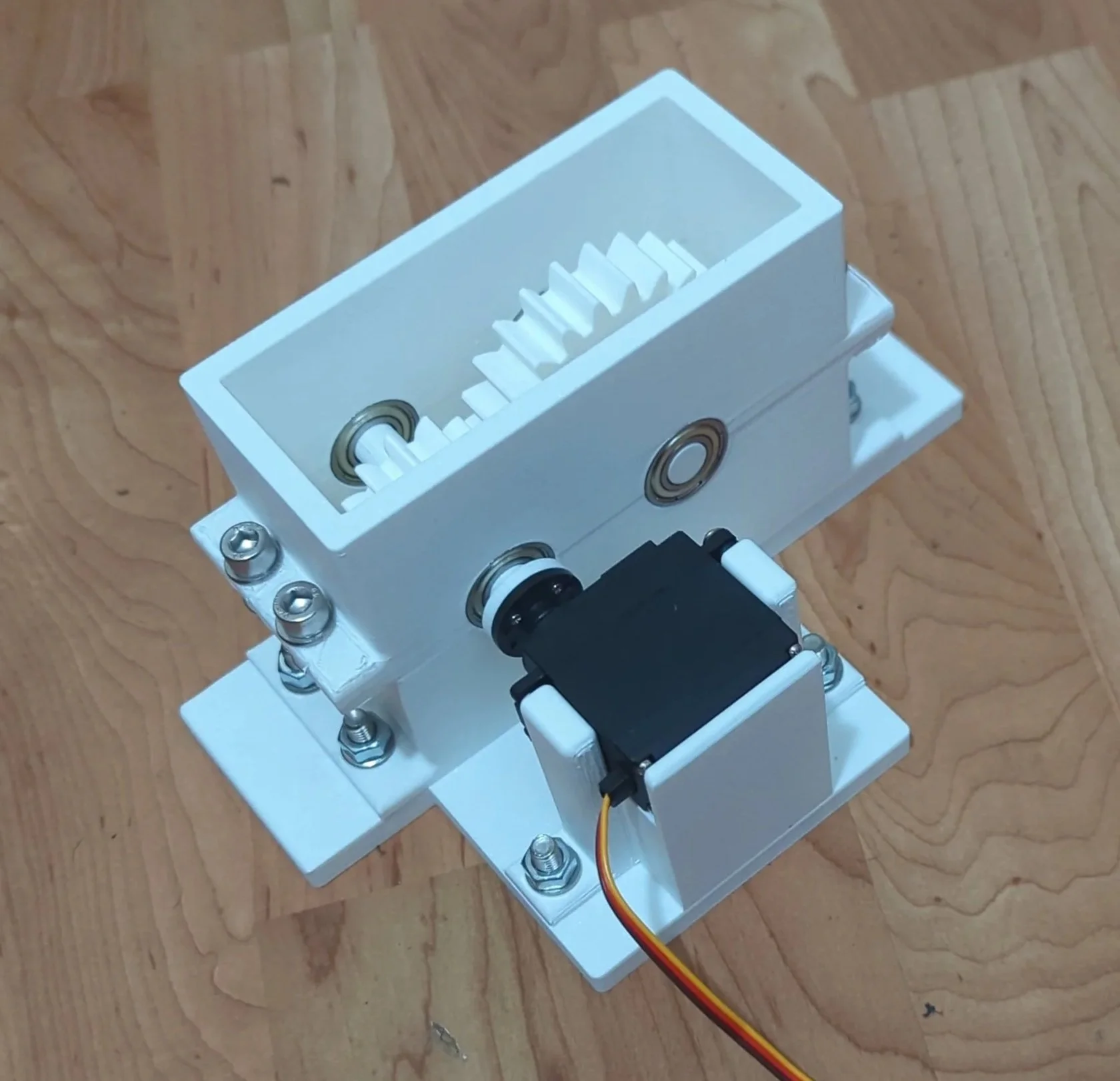
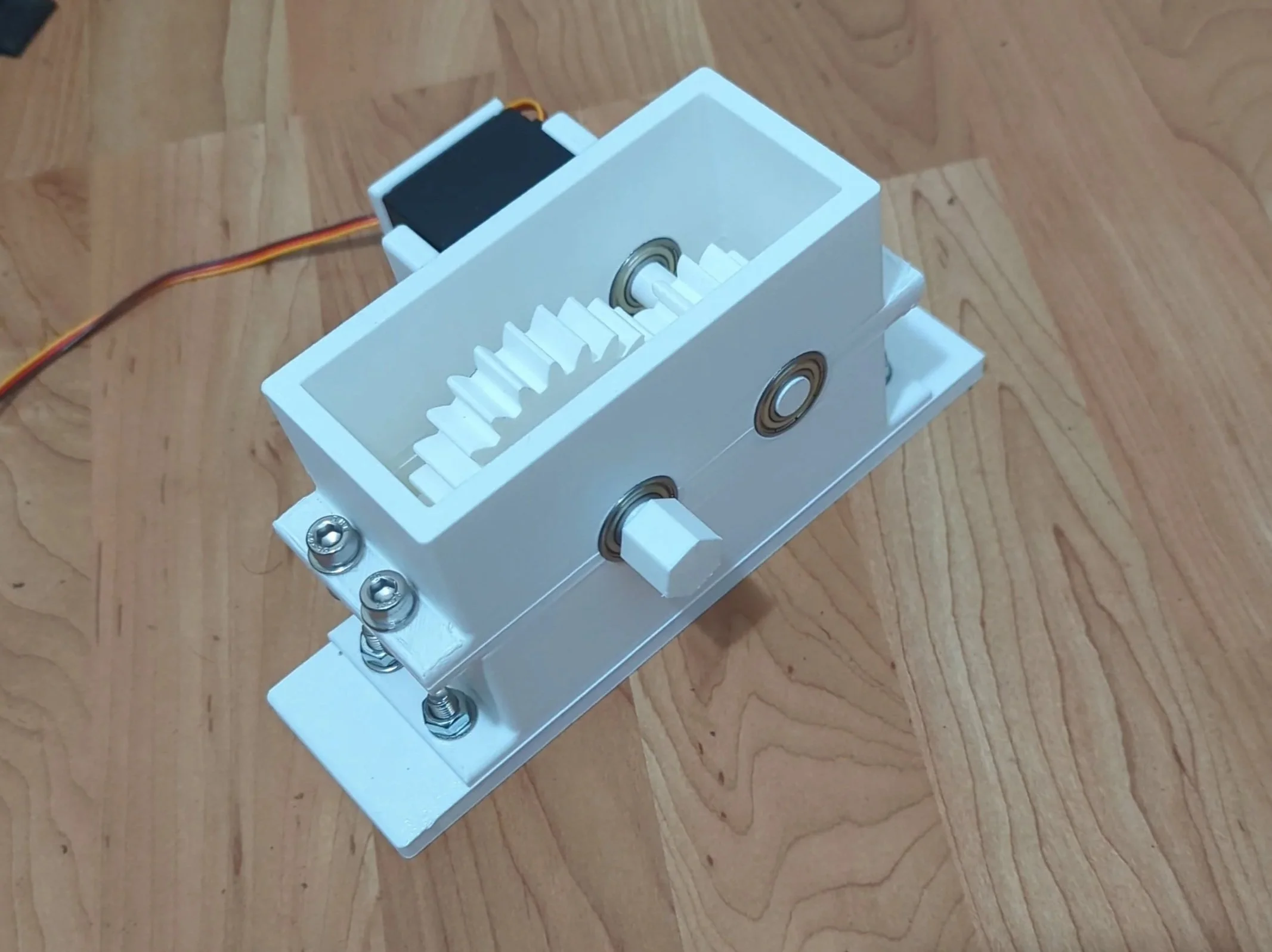
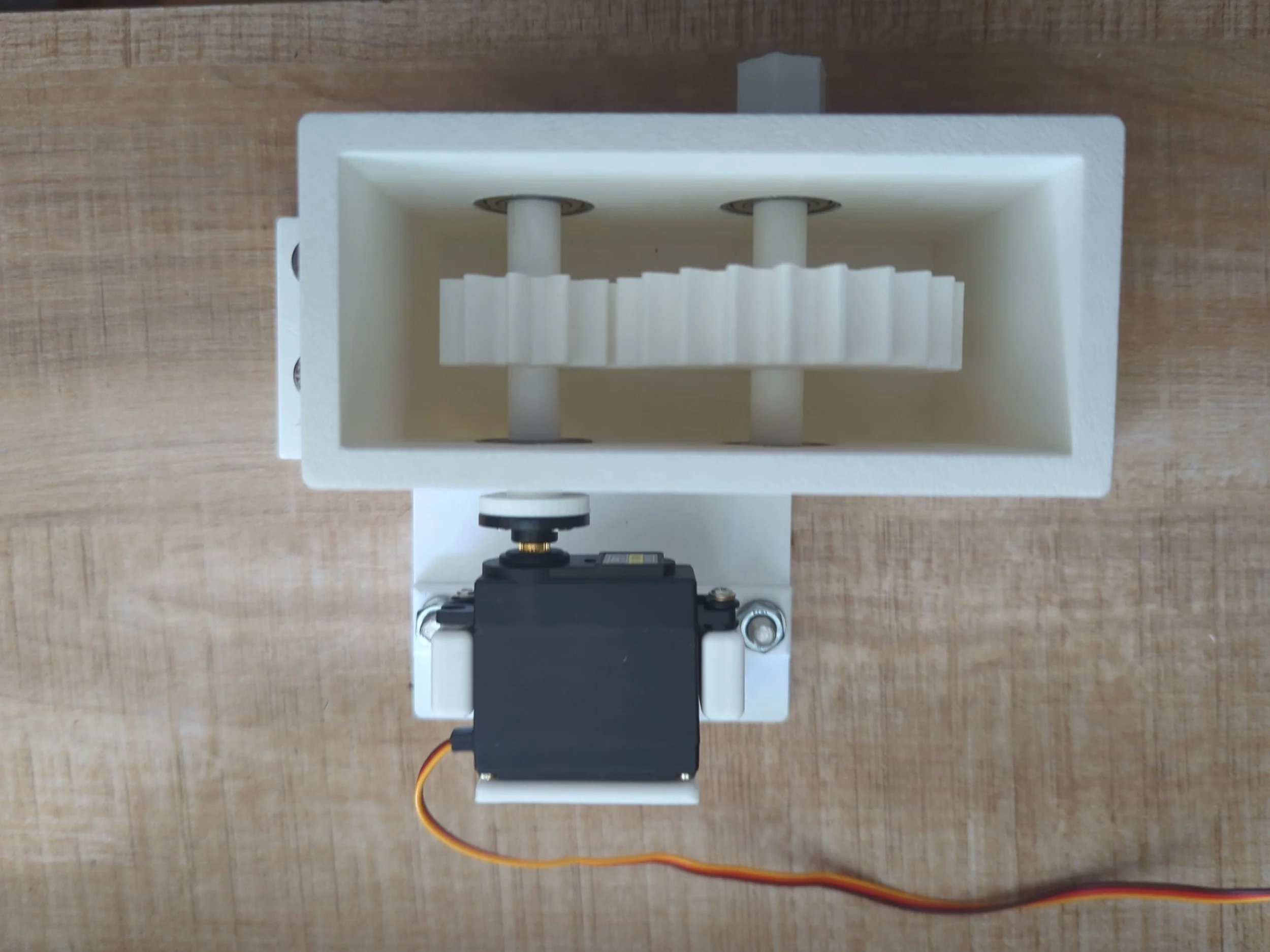
This is the assembled prototype, along with a video of testing the torque output with known weights (more information on this in the testing and validation section below).
To test whether the gearbox met its requirements, I designed a custom lever arm with a a basket at the very end of it, to hold weights. I could then keep adding known weights at the end of the arm until servo stalled, then do some simple math to figure out how much torque the output shaft could supply.
Testing and Validation


Some important notes with this setup, it only measured the stall/static breakaway torque, and the exact maximum weight may be slightly more, since the weights were being added in 5 g increments.
A complete list of requirements against the measured values is given below:

Fails + Lessons Learned
Fail: When the gearbox was first tested, the lever arm that was connected to the output shaft broke off upon having the highest test load placed upon it.
Cause: The hexagonal part of the output shaft that mated with the lever arm was slightly smaller in size than the rest of the shaft, with sharp corners that did not distribute stresses evenly.
Fix: The connector to the lever arm was increased in size, and had fillets added around its edges to reduce stress concentrations.
Lesson Learned: During my initial design, I had left the design of the components related to the validation till the end. This resulted in them being designed separately from the rest of the gearbox, and they did not have calculations to back their design. My main lesson learned was I needed to be meticulous about selecting all components that undergo significant loads, not just the ones in the primary scope of the project.
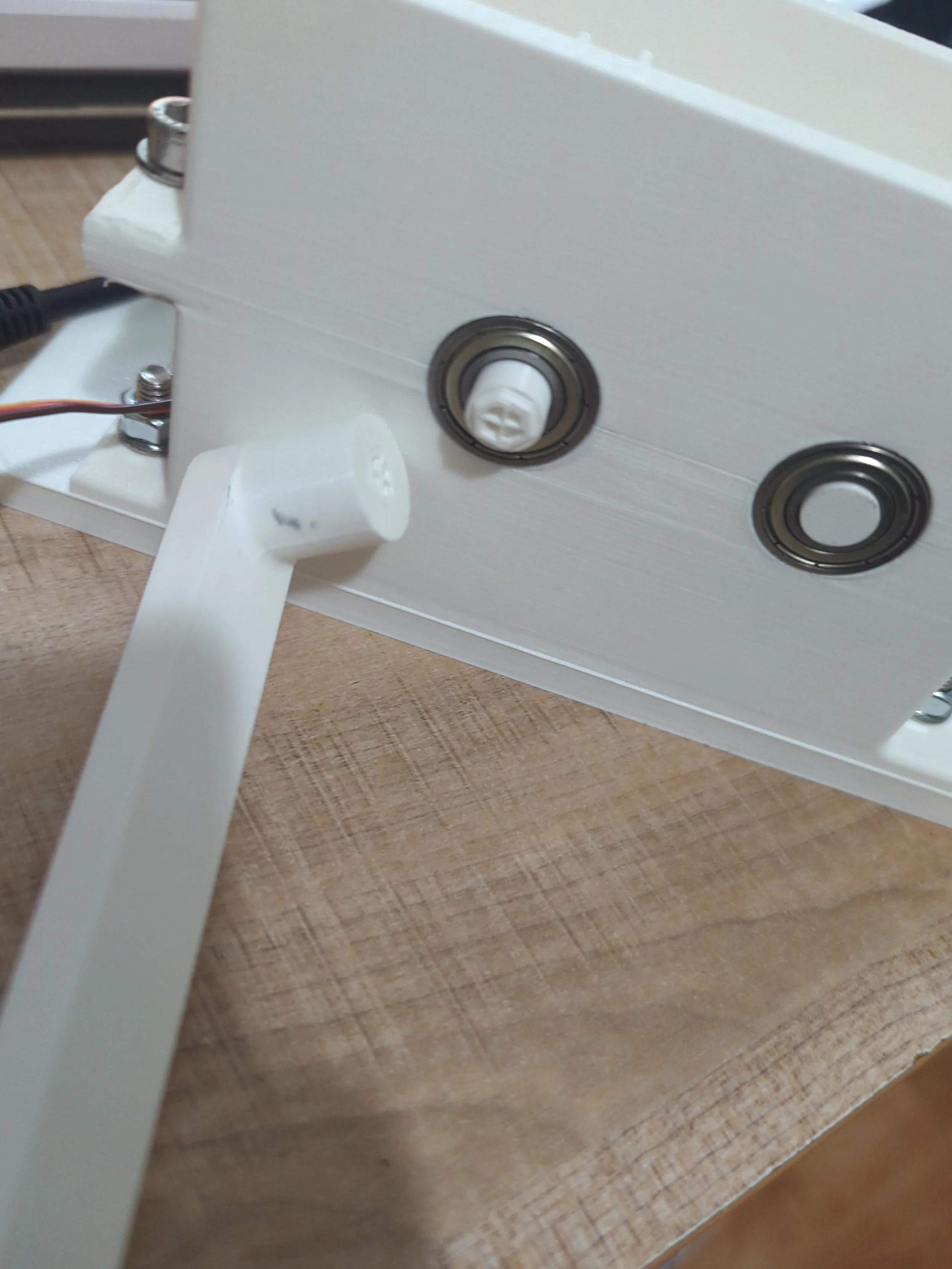
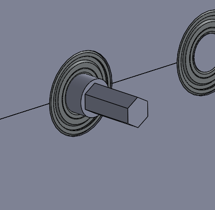
Initial Design
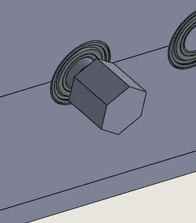
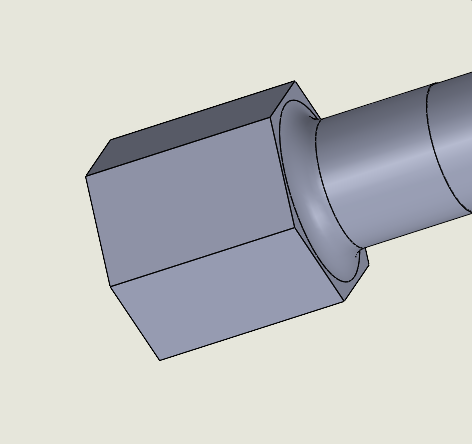
Improved Design
Requirements (2-Stage)
Must be able to able to output at least 20 kg · cm of torque, from a 9.4 kg · cm input servo motor
All components except fasteners and bearings must be 3D printable and have a minimum safety factor 1.5 for all loads they support
Calculations
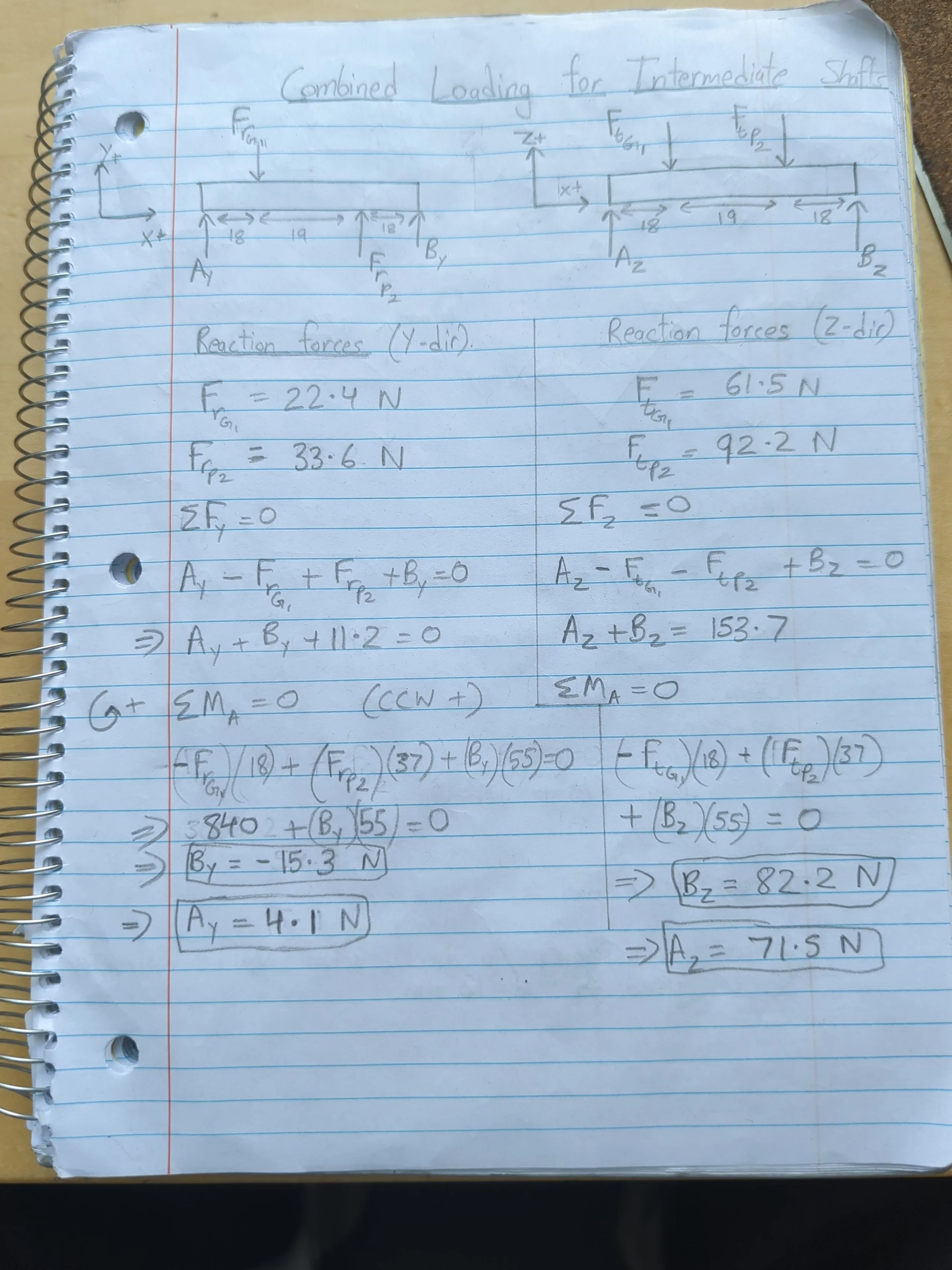
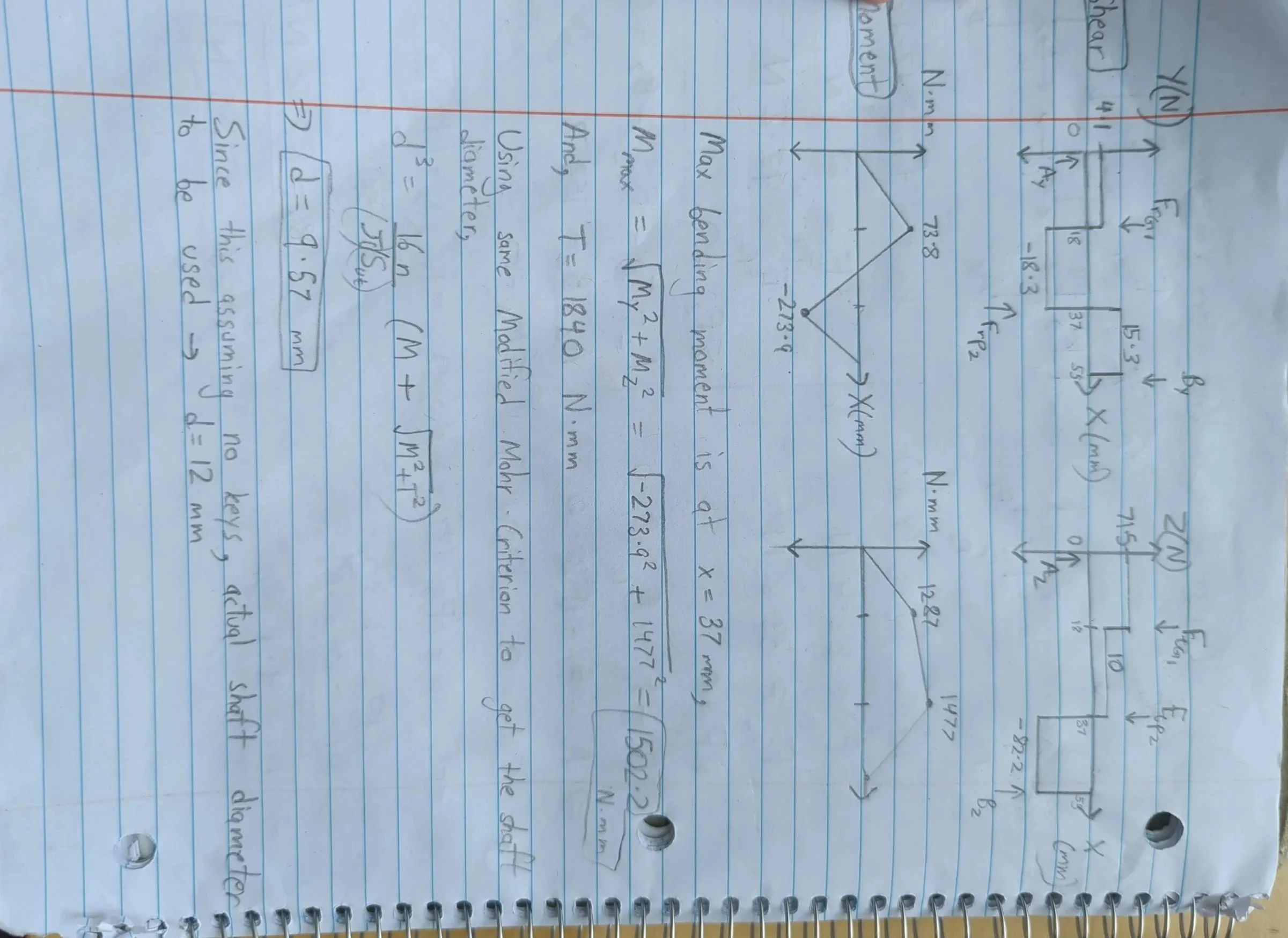
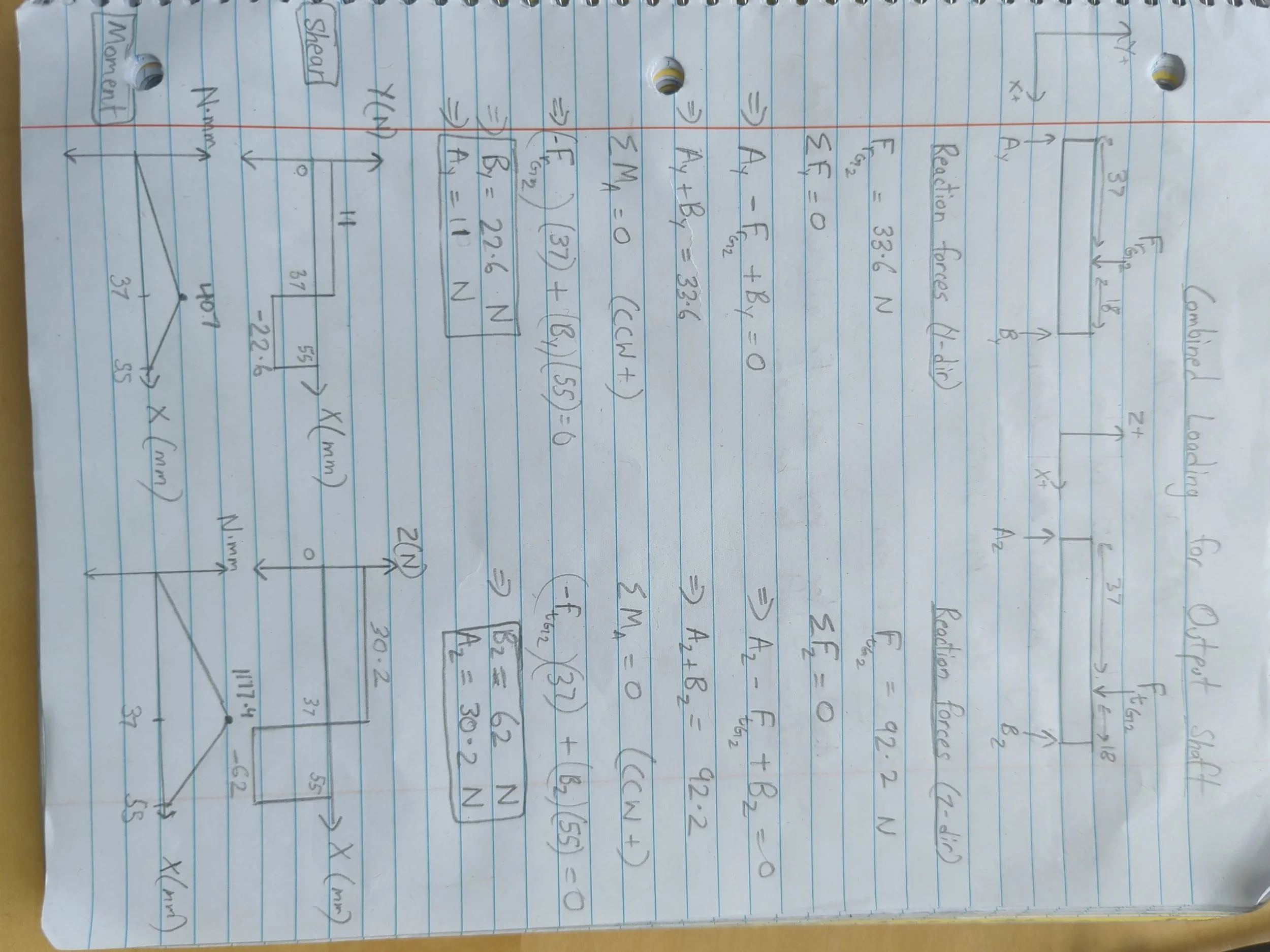
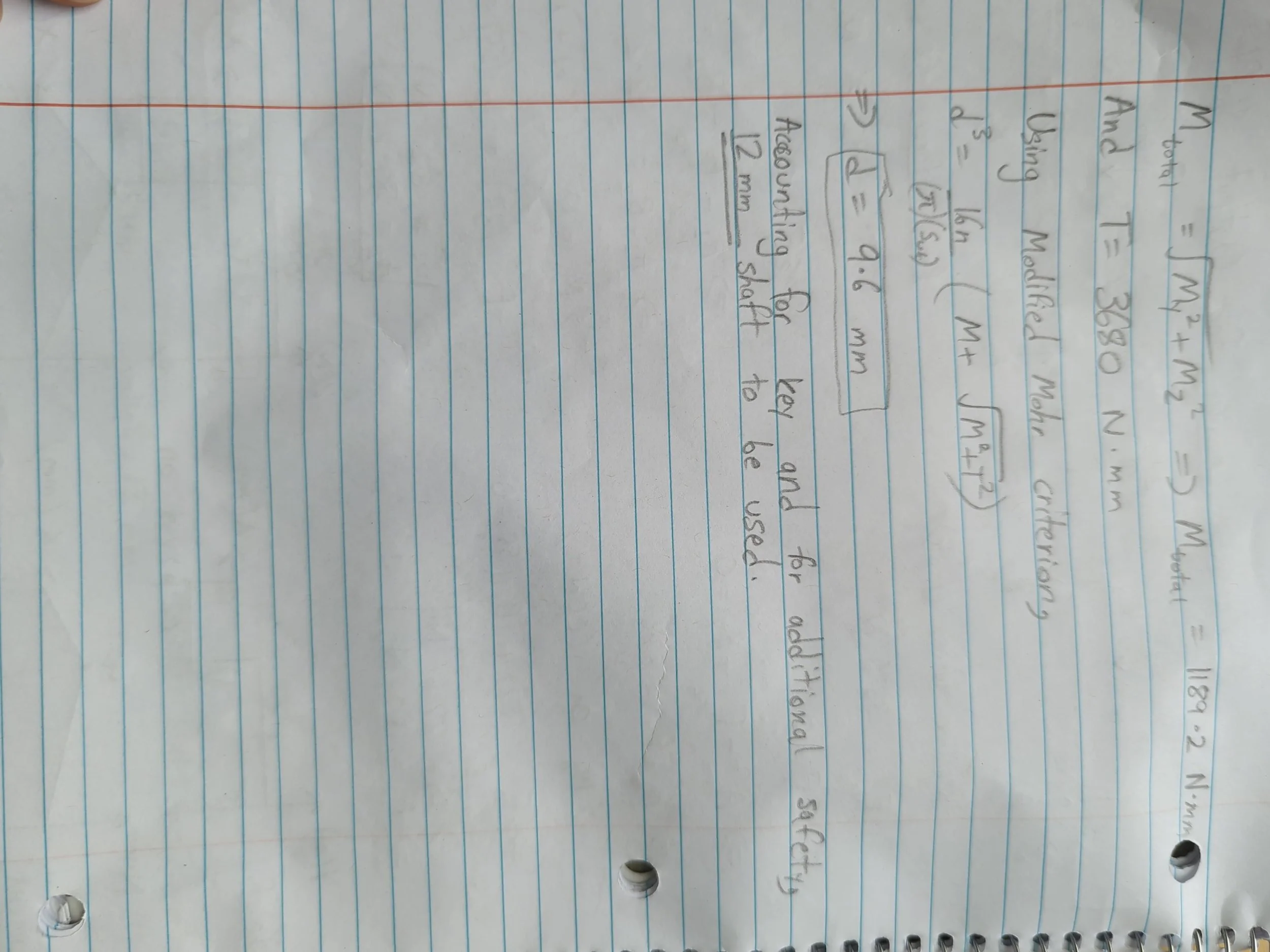
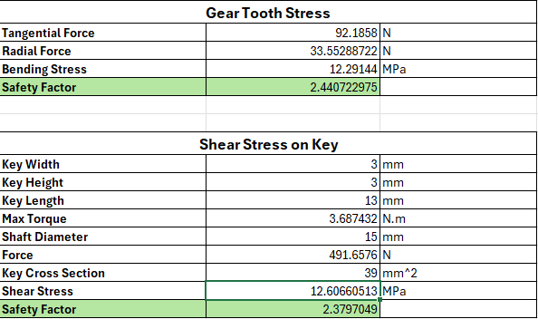
The hand calculations to find the minimum diameter of the intermediate and output shafts (input shaft loads remain unchanged) are shown below, along with the safety factors for the gear teeth and keys (using Excel).
Final CAD
Prototype
Coming soon!