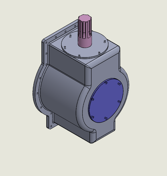
Ship Propeller Gearbox ⚙️
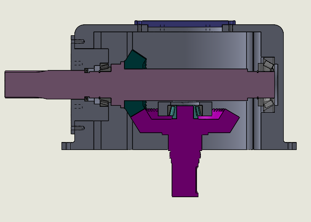
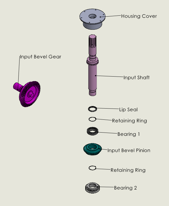
This was a course project for MTE 322, Electromechanical Machine Design. The first goal of this project was to calculate all loads in a 2-stage gearbox with bevel gears, that is used in the power transmission of a ship’s propeller. Then, a custom shaft and housing had to be designed to accommodate these loads, along with any bearing accessories (retaining rings, lip seals, etc.) necessary to complete the design.
Skills Utilized 🔨
Mechanical Design
Component Selection
Fits and Tolerances
Requirements
Selected bearings must have a L10 life of at least 50,000 hours under rated operating conditions, and a static safety factor of at least 20.
Selected retaining methods for bearings must be able to handle axial loads at rated operation conditions.
Calculations
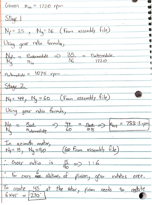
The first half of the project involved calculating the forces placed upon the bearings on the input shaft. To do so, first the gear ratio and speeds for the intermediate shaft were solved for:
Load Calculations
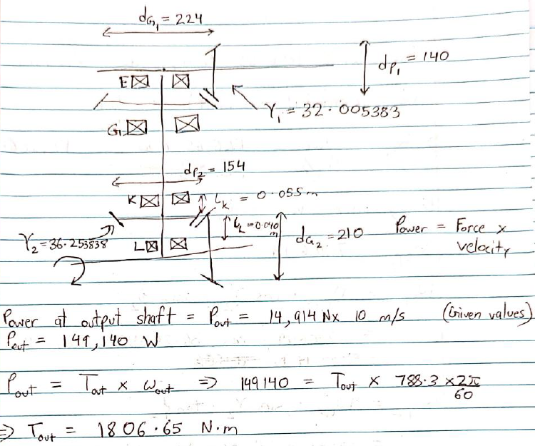
Then the power and torque values:
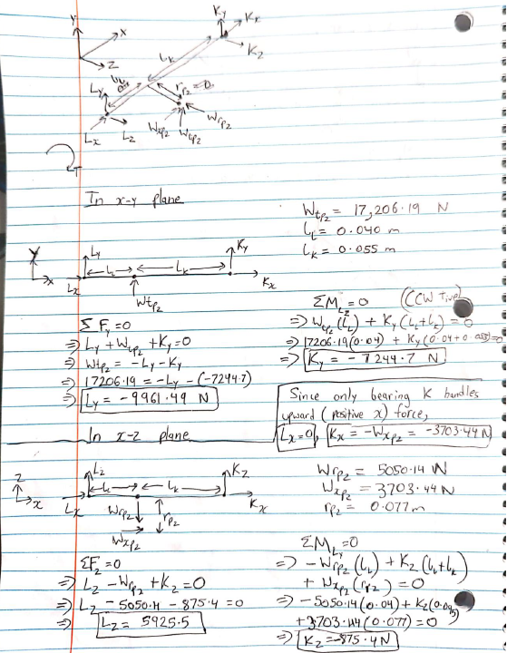
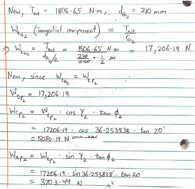
Finally, the tangential, radial and axial forces could be solved for:
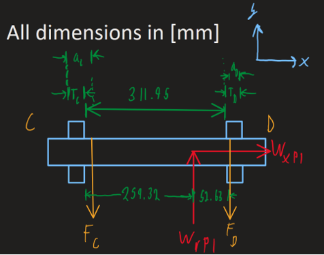
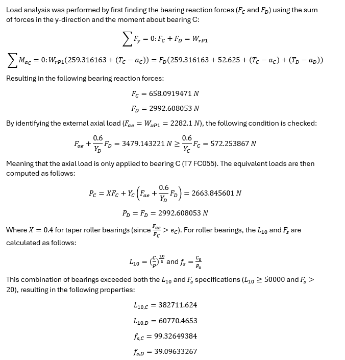
For this application, tapered roller bearings were to be selected to retain the shaft, as they could support heavy axial and radial loads. Since the load calculations for the bearings differed from bearing to bearing because of changing load centers, the load calculations were automated using Excel and the bearings were selected using iteration.
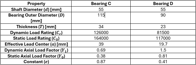
The calculations for the final bearings selected, along with the properties of the selected bearings (from McMaster-Carr) are shown below.
Bearing Selection Calculations
Retaining Ring Selection Calculations
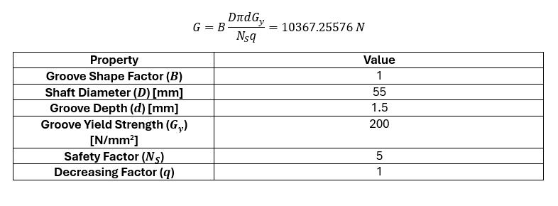
The retaining ring was required to be able to at least support the axial loads placed upon it, which was calculated to be around 2280 N. The groove load calculation along the parameters of the selected retaining ring (selected from McMaster-Carr) are shown below.
Tolerances
Since the inner ring was rotating but the load was stationary from an outsider perspective, an interference fit (m6 tolerance) was selected for the shaft and a clearance fit (H7 tolerance for housing/g6 for shaft) was selected for the housing.
Final CAD