Lift Assist Platform ⚙️
This is a WIP project in which I aim to build a lift assist tool for battery modules (and repurposable for other heavy weights of upto 30 lbs), using 2 synchronized lead screws.
Skills Utilized 🔨
Mechanical Design
Finite Element Analysis
Milling + Lathe Machining
Design for Assembly
Must be able to able to lift at least 30 lbs of weight, and the platform must be sized to fit the University of Waterloo’s battery module (585 mm x 215 mm x 114.33 mm)
At its highest point, the vertical height of the platform should be at least 0.5 m
The lifting force must be equal to or lower than 7 lbs
The platform must not exceed 750 mm in both length and width (designed to be able to fit through doorways)
Requirements
Engineering Challenges
Designing a guiding mechanism to prevent the lift to stabilize lift by supporting lateral loads
Synchronizing motion of lift platform, avoiding misalignment and self-locking
Designing platform for ease of user, ensuring safety under all circumstances
Designing for manufacturability, and selecting appropriate tolerances for all components
Initial Ideas, Sketches
The initial design idea had 4 lead screws, and a hand crank at the bottom with bevel gears for easier access.
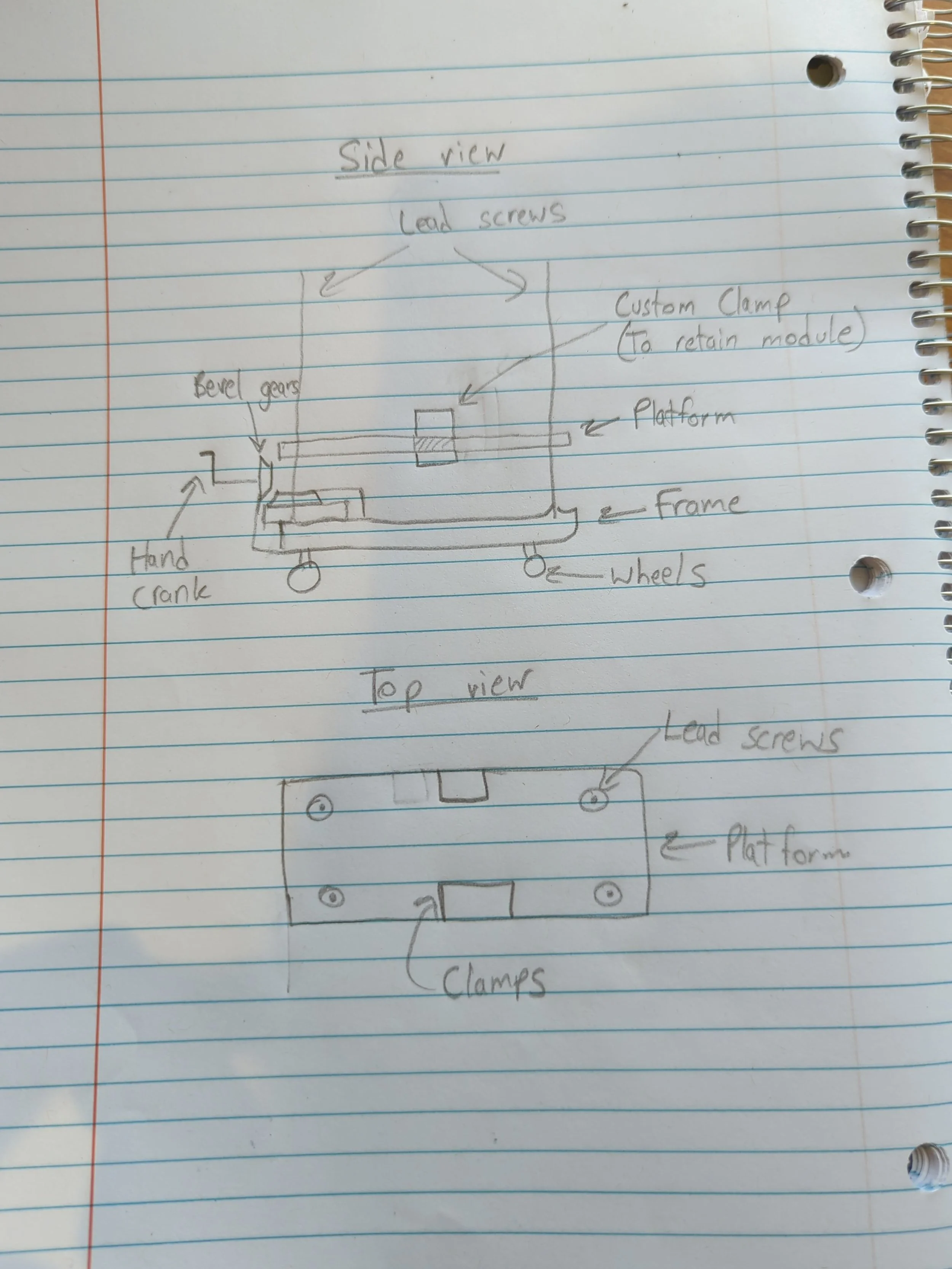
Main design changes by the end of the design process are highlighted below:
Hand crank positioned to the top without bevel gears, for ease of assembly.
2 lead screws used, easier to synchronize motion this way and can sufficiently support required loads.
Locating pins added to the platform, standardizing the placement process and ensuring battery module stays stable during transportation.
Frame extended vertically, with 3D-printed guide rails added, constraining lateral movement of the platform as it lifts the module.
Ball bearings added to the top of the lead screws, and thrust bearings added to the bottom of the lead screws, to support radial and axial loads on the lead screws.
Calculations
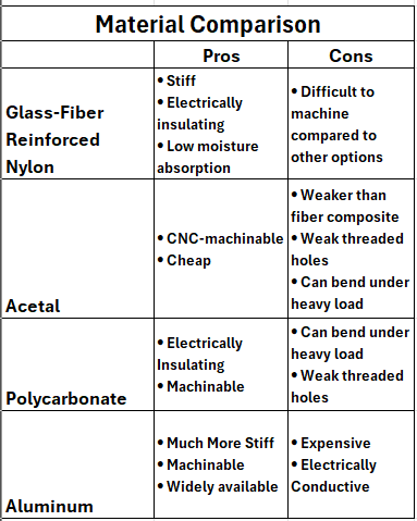
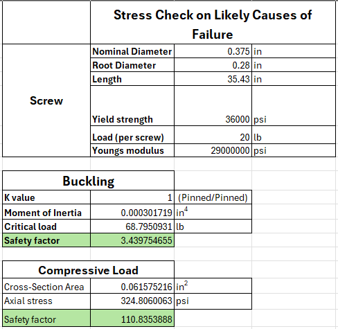
Given the material options, I decided to go with aluminum given it was the best combination of stiffness, strength, and manufacturability. With added insulation (in the form of mylar or PET film) it would also be safe to interface with battery modules.
For preliminary stress calculations, I started with a simple compressive load calculation then used Euler’s critical buckling formula to check for the buckling safety factor.
FEA Simulations
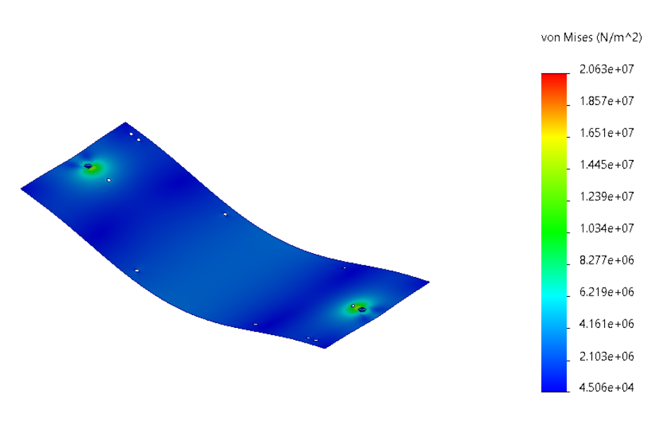
FEA simulations were performed using SolidWorks to determine how well certain components would hold up under certain loading conditions.
These also helped to iteratively select components of the appropriate sizes. For example, the initial thickness for the aluminum base plate was set to be 1/8” but upon running a static analysis and revealing it would fail under loading conditions, the thickness was bumped up to 1/4”.
The failing conditions tested through FEA simulations were buckling for the lead screws and bending stresses on the base plate.
CAD iterations
The initial design contained the barebones of the design, with thrust roller bearings at the bottom to handle axial loads, 2 vertical aluminum extrusions along with custom guide rail parts fastened to the base plate, and a hand crank at the top to move the platform.
The next iteration’s main addition was wheels with casters to move around the platform. In the third revision, ball bearings to handle radial loads were added near the top of the lead screw, and to lessen misalignment of the lead screws. The wheel mounting was also moved to the bottom of the extrusions, rather than the sides, to increase stability.
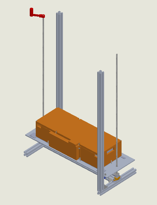
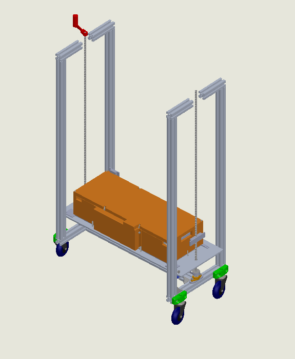
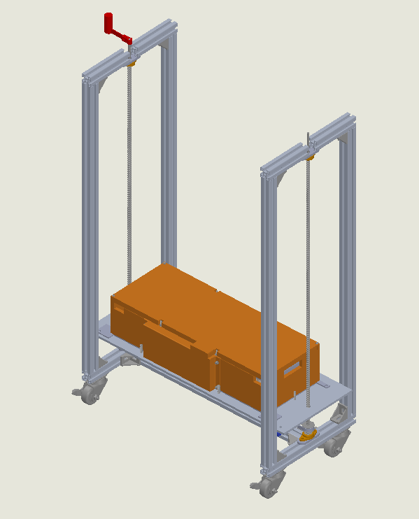
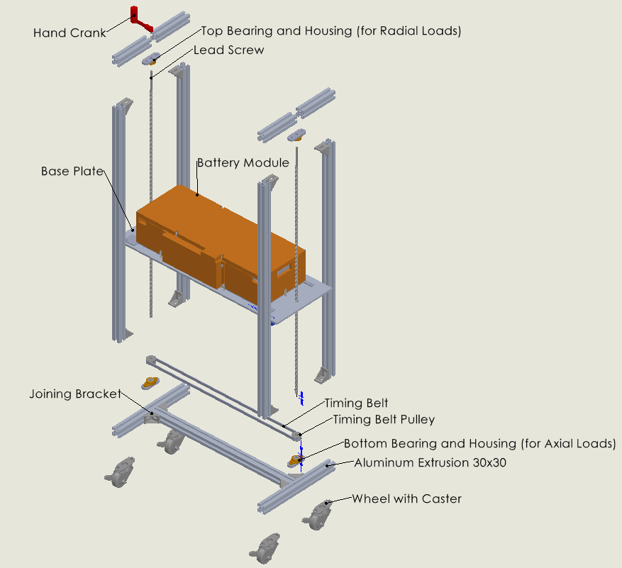
A labelled, partially exploded view of the CAD is shown below.
Part Drawings
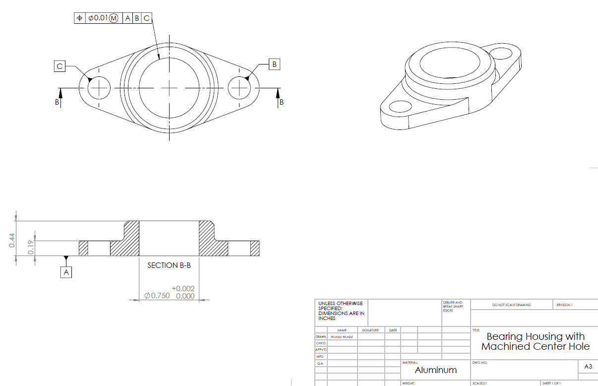
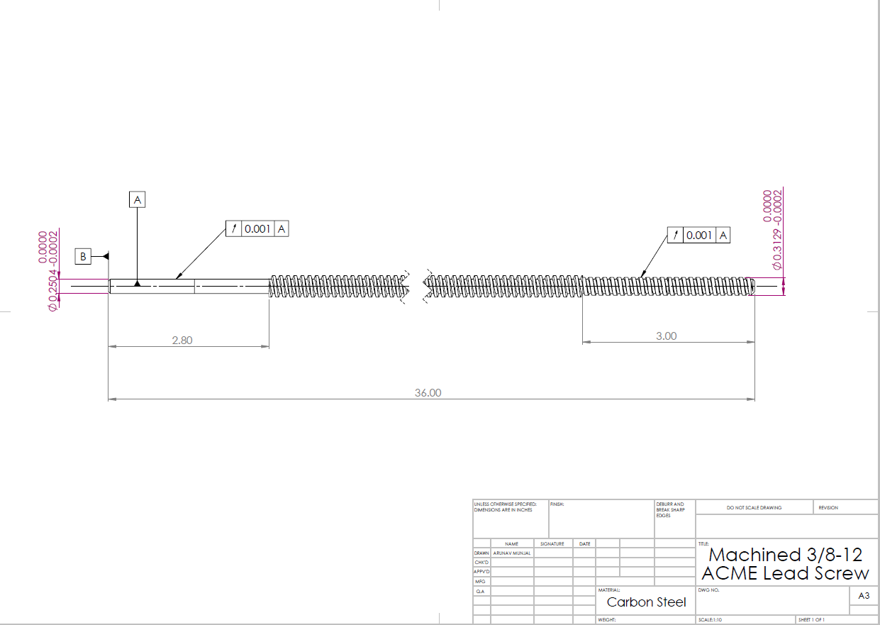
Some parts, such as the bearing housing, had to be machined (bearing housing hole in this example) to the appropriate sizes for them to assemble correctly. For practice I made machining drawings for them using GD&T standards.