Battery Module Design 🔋
This was a 4-month long project for the Battery Workforce Challenge (BWC) competition. It involved designing a packaging solution for manufacturer-provided battery modules, along with voltage and temperature sensing strategies, requiring proper mechanical, electrical and thermal integration. The end goal was to make a safe and robust solution to be mounted into a Stellantis Ram ProMaster EV’s Battery pack.
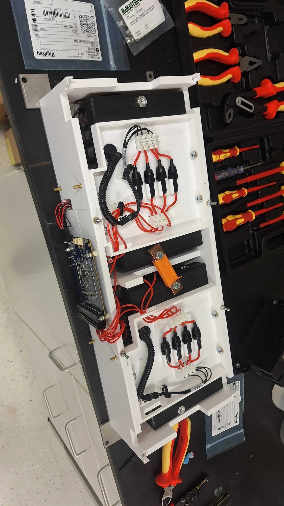
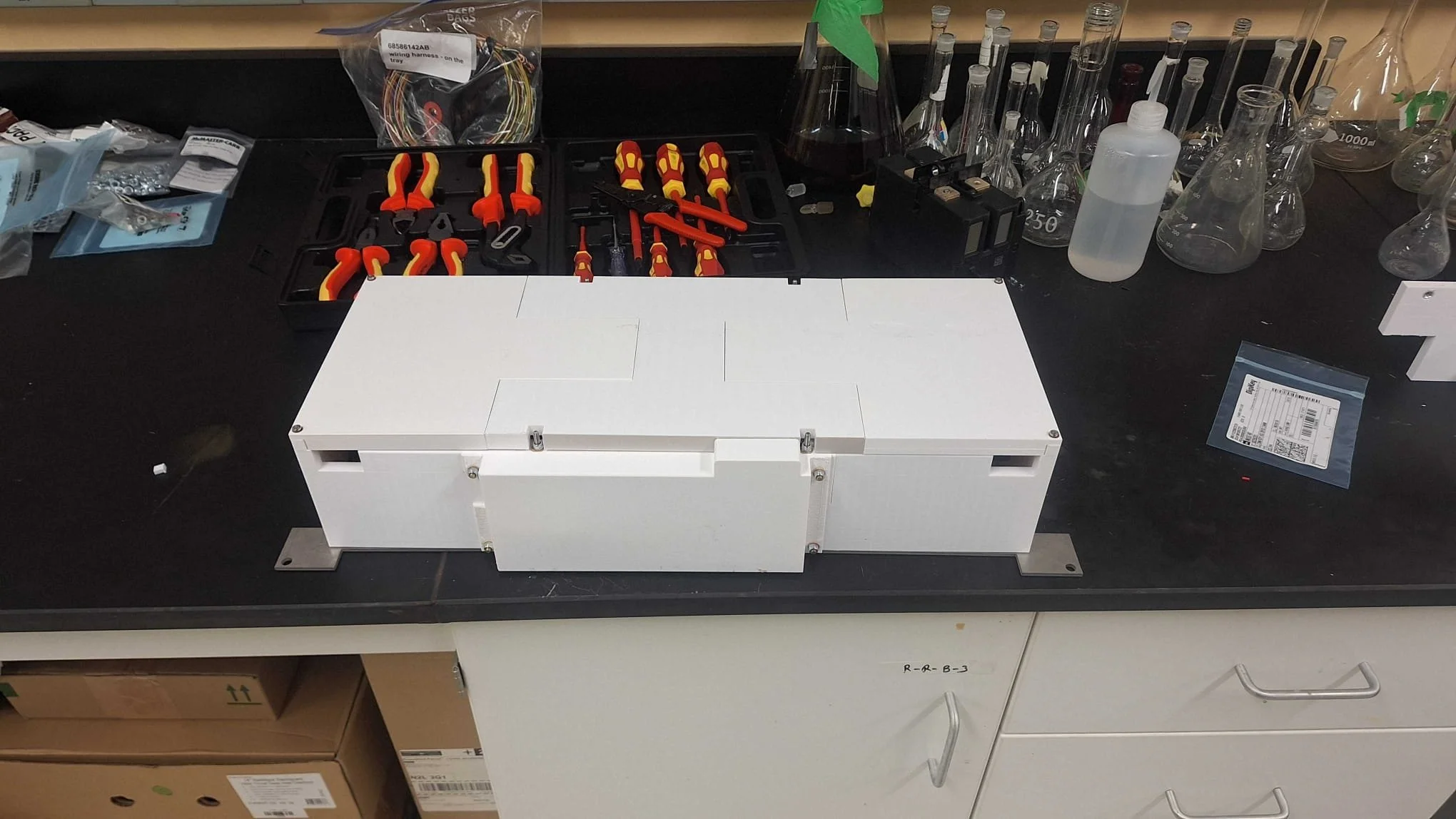
My primary role in this project was the mechanical design of the module housing, along with creating the wiring harnesses for the voltage and temperature sensors. I also fabricated the end components and assembled them to create several prototypes.
Note: Several images have been modified/omitted from this project, since they contained confidential data from Stellantis/other manufacturers. Only certain views of the battery modules themselves are shown.
Skills Utilized 🔨
Mechanical Design
Design for Manufacturing + Assembly
Milling Machine + 3D printing
Fits and Tolerances
The competition had a lengthy list of requirements, for brevity, only the most critical and relevant ones to the project are listed here.
All High-Voltage (HV) components must meet creepage and clearance distance requirements
Voltage sensing lines and fuses must be retained securely, along with the fuses being in serviceable locations.
All wiring harnesses must have retention clips placed at set distance intervals.
Insulating components must have a dielectric protection for a 800 V system.
Design must be able to hold up under automotive vibration testing conditions.
Requirements
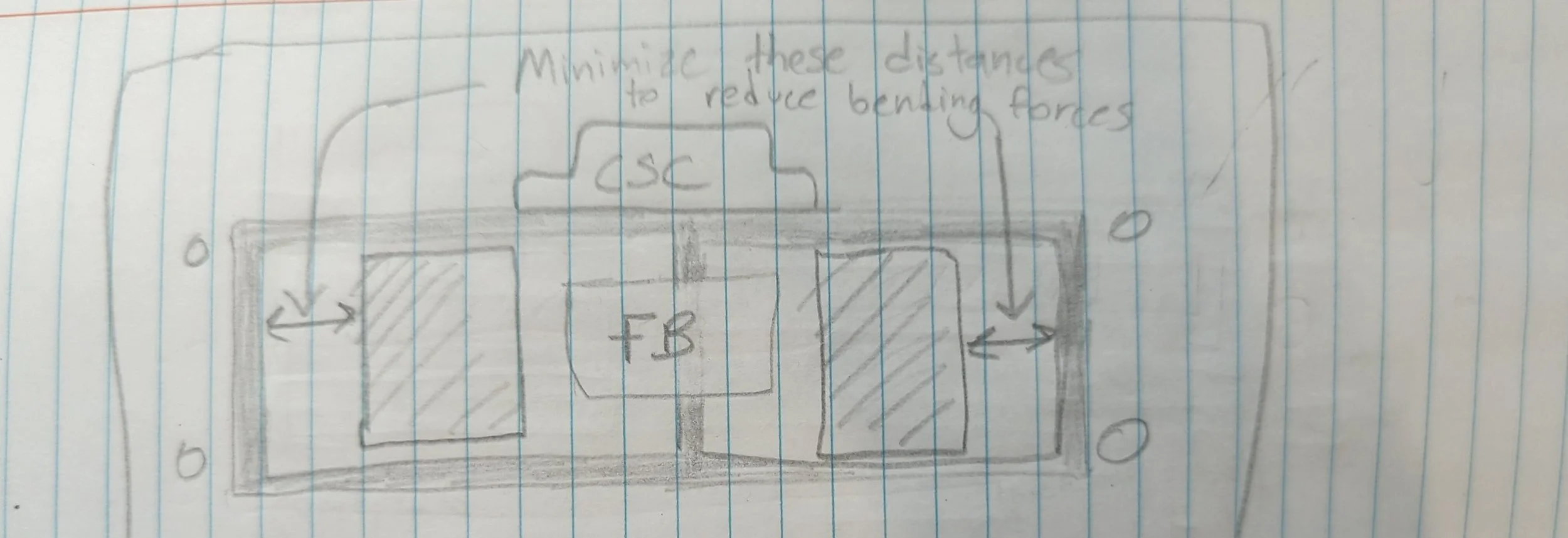
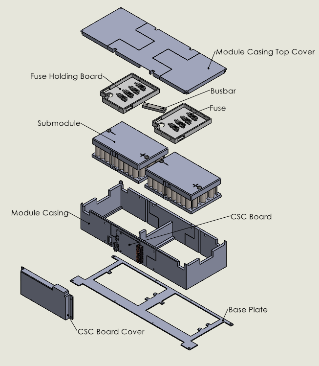
The design underwent multiple iterations. The main hurdle to overcome was to figure out how to mount the casing/housing of the modules to the battery pack, which had limited mounting holes located far apart. One module comprised of 2 submodules connected in series via a busbar, each having 63 cells in a 3s21p configuration, for a combined 126 cells at (roughly) 25 V in a module.
Additionally, the cells were cooled by an aluminum cold plate, isolated from the battery modules via a thermal interface material (TIM). The TIM had to be selected such that it was thin enough to transfer enough heat, but thick enough to have a dielectric strength of 800 V.
Initial Ideas, Sketches
Iteration 1: Press-fitting the modules to the casing, then mounting the casing onto the battery pack
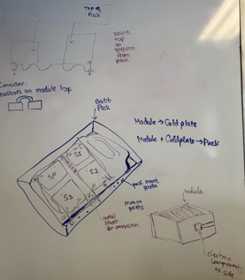
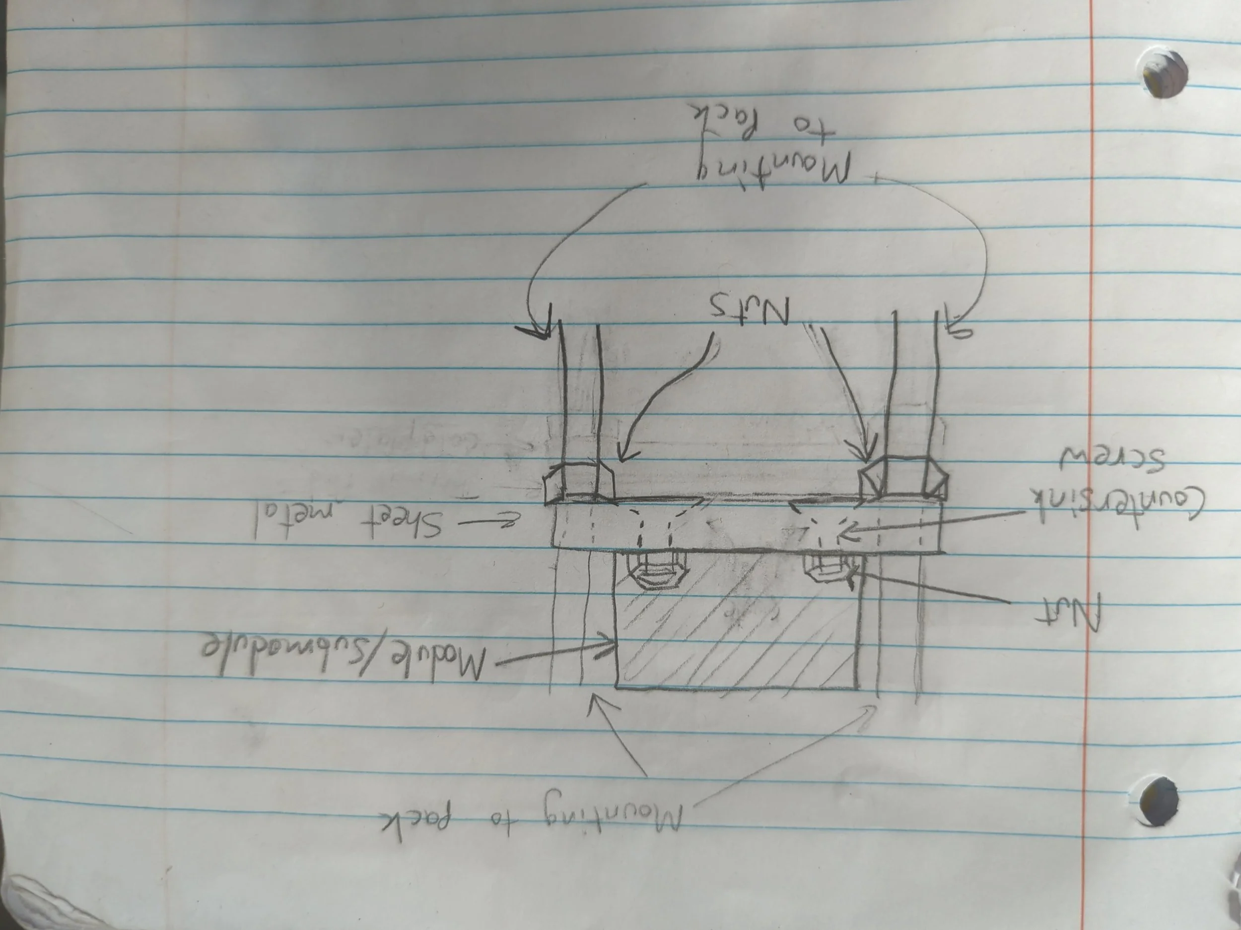
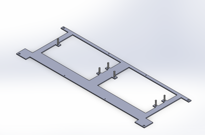
Iteration 2: Base plate design that held the modules by fasteners, then mounting this base plate onto the battery pack
The previous iteration could not retain the module accurately in the z-direction and also posed assembly issues once wiring was involved. A better solution that used fasteners was required.
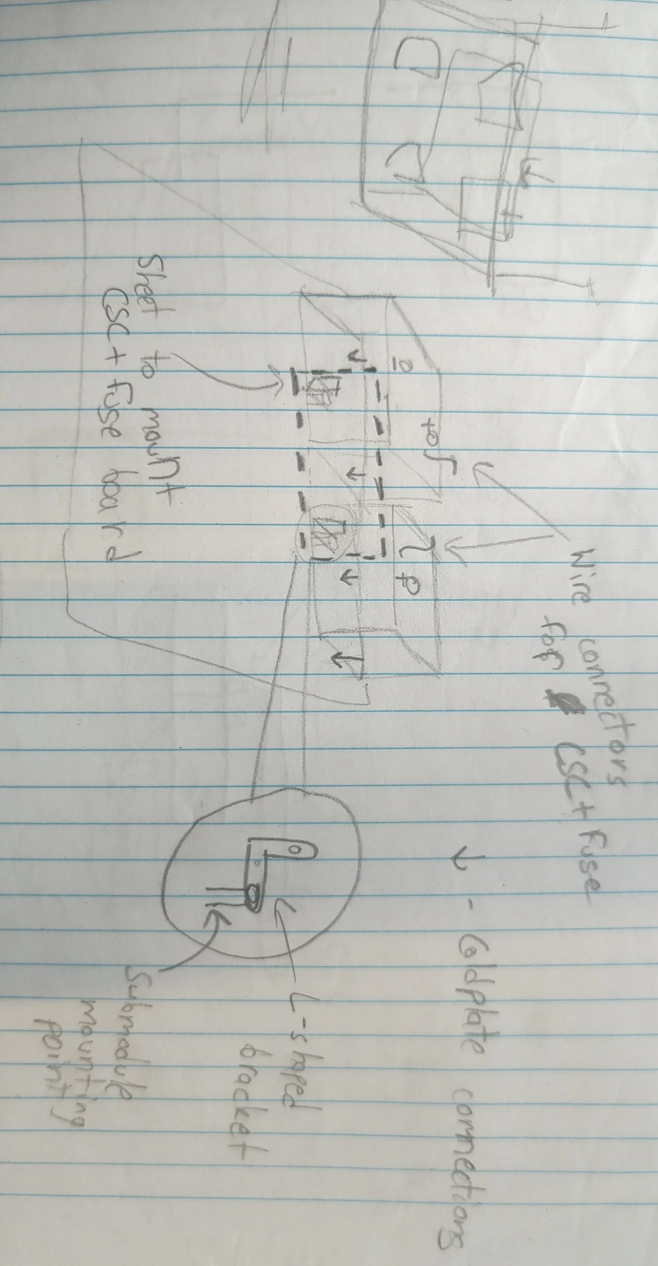
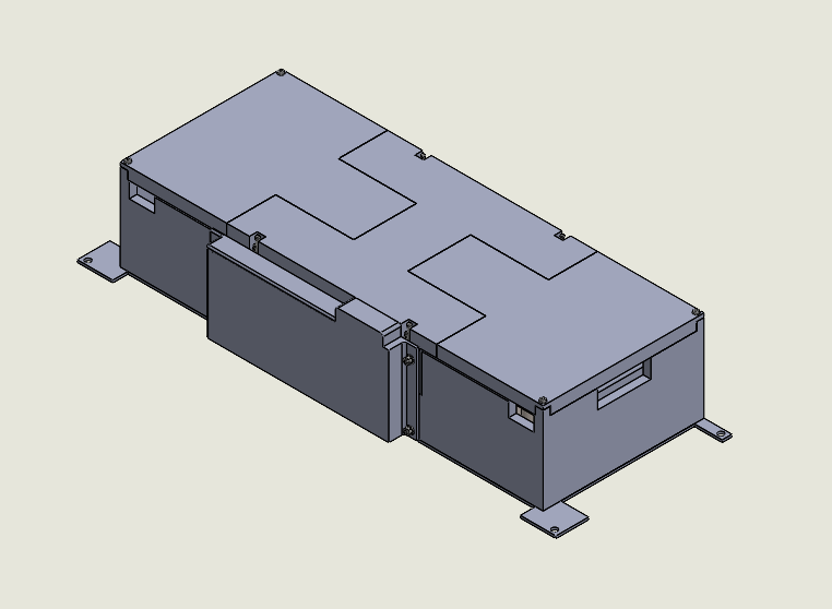
Iteration 3 (Final): Changing orientation of modules, modifying base plate to be mountable to the pack
Upon pack integration, it was discovered that although the module packaging design was sound, it occupied too much space for other pack components to be placed alongside it, such as the battery management system, high-voltage and the low voltage wiring. The submodule orientation had to be flipped, along with re-working the wiring for the fuses and the voltage/temperature sensing lines.
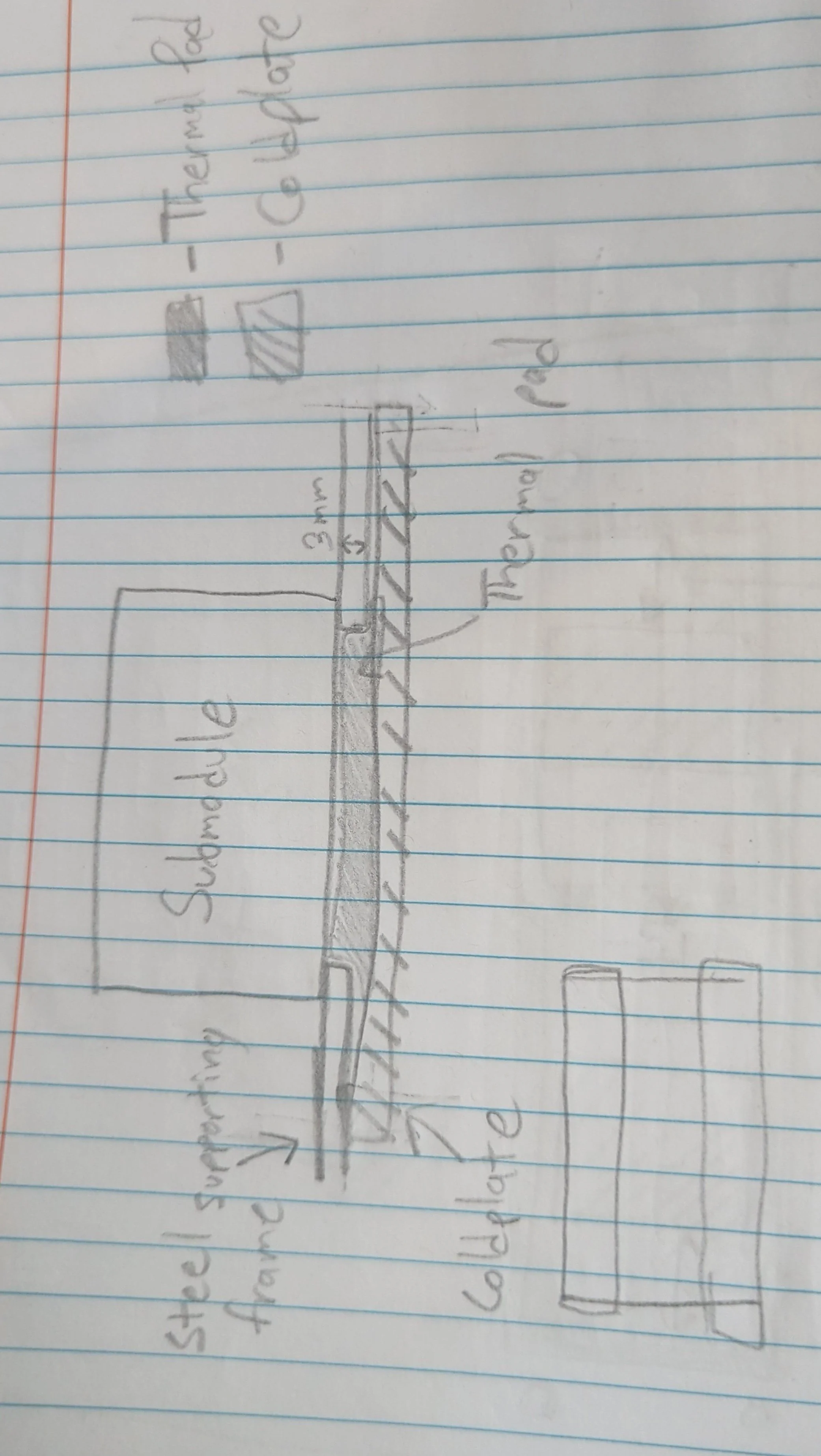
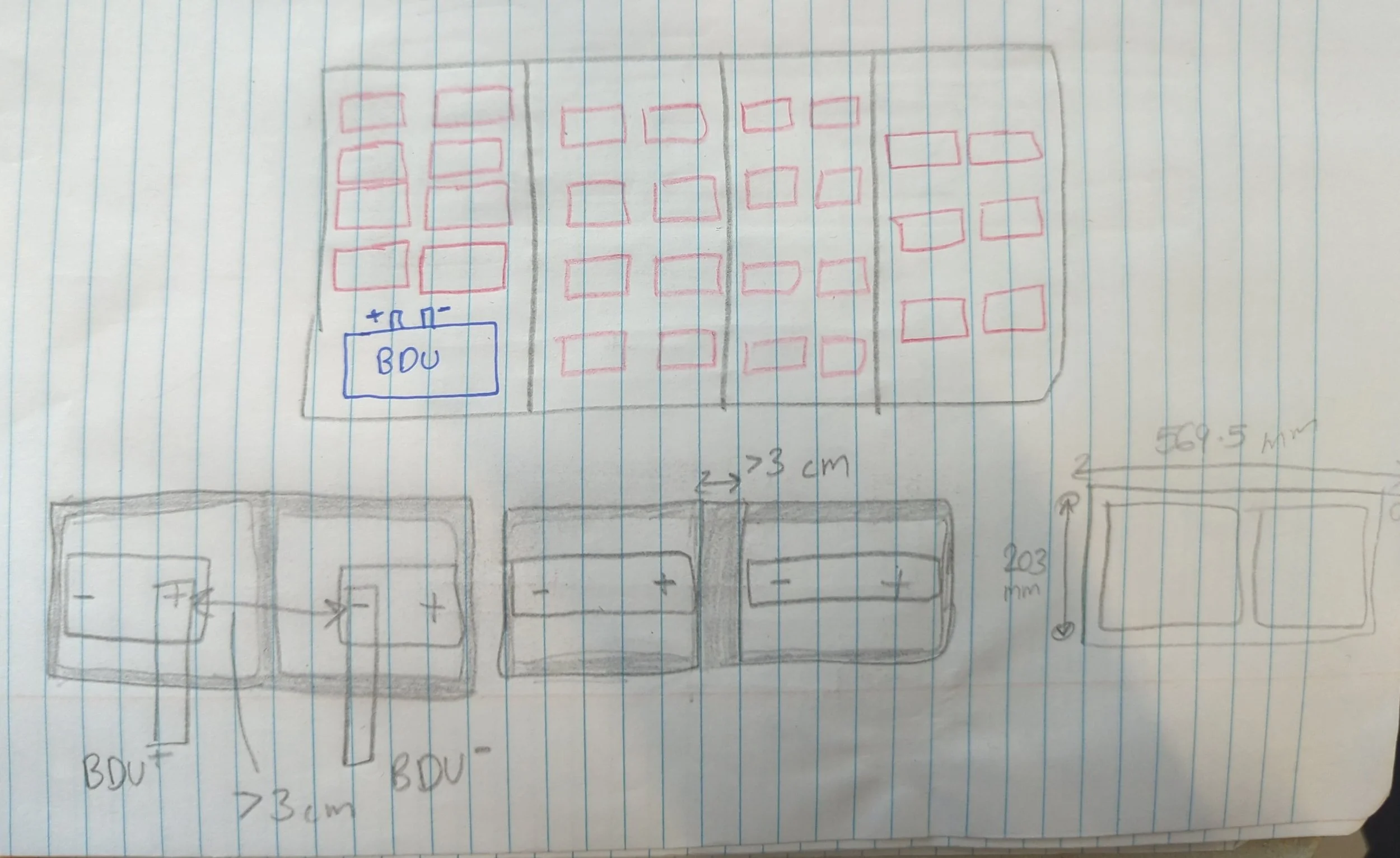
Calculations
To select an appropriate thermal interface material, I wrote code in MATLAB that calculated the amount of heat that was transferred to the aluminum cold plate and whether that heat transfer met requirements. The code can be found by clicking here.
CAD models + Prototypes
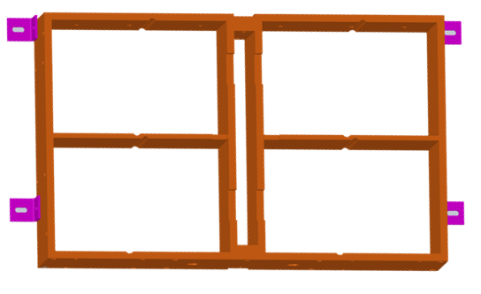
Press fit design (modules removed for clarity):
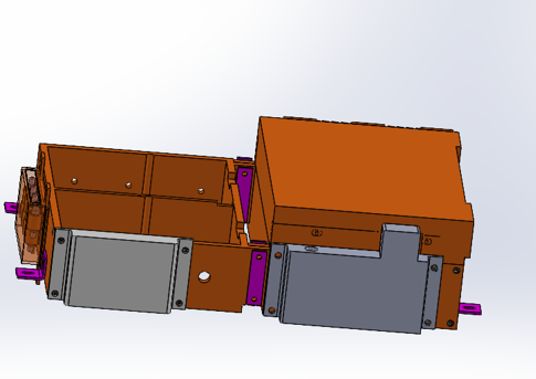
Adding fuses and the current sensing circuit (CSC) board, for gathering readings from the voltage and temperature sensors:
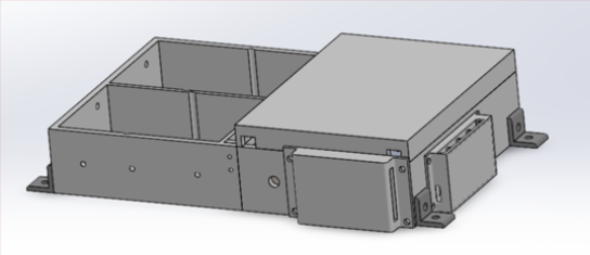
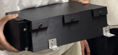
Bit too high for the battery pack, re-designing the fuse retainers (underneath the top cover)… Also, the first prototype!
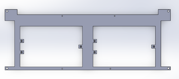
Designing a base plate to retain the submodules, then adding the fuse holding components on top of it… Along with the final manufactured design.
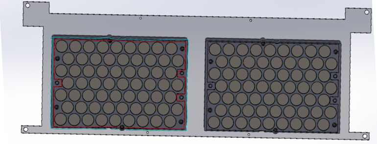
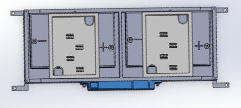
Top and bottom view (with the submodules), with added tabs to support their weight
Fabrication/Manufacturing
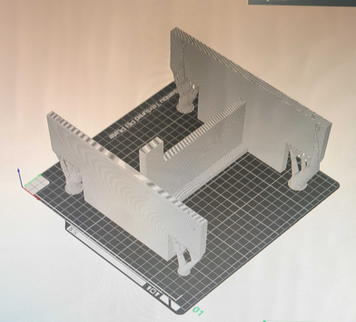
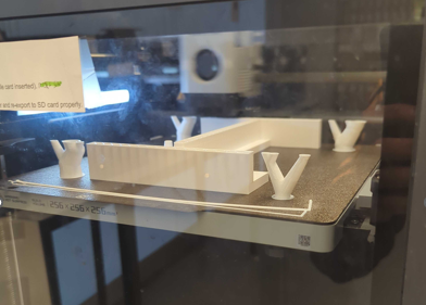
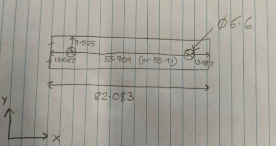
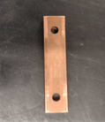
I fabricated the module casing parts through 3D printing, and the busbar connecting the 2 submodules was cut down from a copper bar by a milling machine, for which I got the tolerances correct down to ±0.05 mm
Assembly Documentation
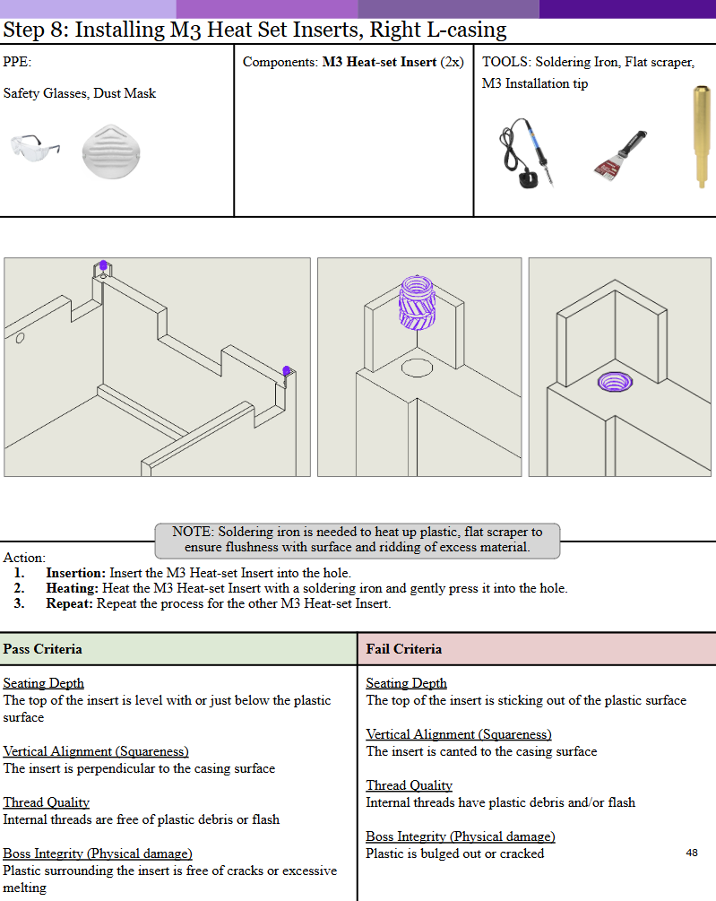
Upon completion of the design, a build book documenting the entire build procedure, part tracking, spec data, and additional logs was drafted collectively by the UW EVolution design team. An example page along with a pdf link to the entire build book is shown below, check it out!